Skip to content
Welding Gear
Make Money
Guides
Careers
Health
Education
Toggle Menu
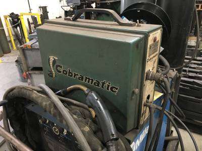
aluminum-wire-welder-cobramatic
Welding Gear
Make Money
Guides
Careers
Health
Education