How to Setup Your MIG Welder – A Helpful Guide
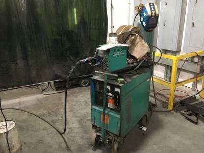
When you’re ready to MIG weld, you need to prepare a few things. Obviously, you need a safe workspace. You also need a thoroughly cleaned and prepared base material. You also need to make sure your MIG welder is optimized for the best possible performance and strong weld.
How do you set up a MIG welder? Setting up a MIG welder requires several tasks. This will include things such as considering the type of metal, the thickness of metal, preparing your work area, voltage and gas settings, wire speed, and safety precautions you should take.
If you want to know how way to set up your welder in the best way, then you have come to the right place. Whether you’re wondering how to set up your MIG welder for gas or another material, we will discuss it. Settings for how to set up your MIG welder for flux core, stainless steel, and aluminum are all covered.
How to Setup Your MIG Welder – Advanced Preparation
Before you set up your MIG welder, you need to make sure that you do some research.
The settings differ based on several factors, and there is no single right answer. High-quality welds all depend upon the right MIG welder settings and machine preparation for the best penetration.
Therefore, you will need to know the type of metal, how thick it will be, how you plan to prepare your joint, what gas and electrode (or filer wire) you need, how your welder is set up, and where you can find a few MIG welders setting charts in case you forget.
Safety First!
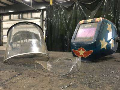
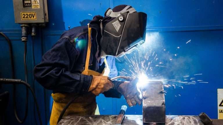
Before you start working with your welder, remember to observe safety regulations when working with this type of material! You should be wearing an auto-darkening helmet, some thick, flame-resistant clothes, closed-toed shoes, earplugs, and long gloves.
You also want to prepare your workspace. Make sure that you’ve cleared away any dust, debris, and extremely flammable material. You should also have some grounding material within reach. Set out your materials so that you can easily access them.
Don’t forget to clean and prepare your material. You want to remove all the contamination from the surface of your base material before welding. This includes dust, oils, rust, and mill scale.
Type of Metal to Weld
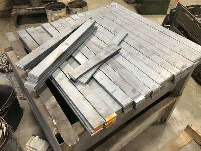
Your base metal has a huge effect on the settings of your machine. IT also affects the type of gas and electrodes that you will need to use. Different types of metals all have different melting temperatures. They all hold and diffuse heat differently, too.
When you set up your MIG welder, you will have to know exactly what type of metal you plan to weld. No single setting can handle every type of metal. The most common materials are carbon steel (commonly designated for sale as A 36 Grade), stainless steel (and nickel-based alloys), and aluminum (or nonferrous metal).
Metal Thickness to Weld
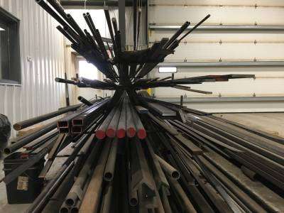
Another important aspect of your machine’s settings for welding is how thick your base metal is. With stick and TIG welding, you can use the same setting for virtually any metal thickness you use. You can even use the same settings to weld both a ¼ inch plate and a 1-inch plate!!
With MIG welding, you need different settings for the different thicknesses of metal. The largest aspect when it comes to your heat settings is the metal’s thickness.
The biggest issue to worry about when it comes to the quality of your weld is using a heat setting that is too low. MIG welding is pretty much banned in nearly all aspects of Nuclear Power Plant building because in the past, a lot of welders didn’t use enough heat and their joints did not penetrate well at all.
Aesthetically, the weld looked fine, but with just a couple hammer taps the joints all fell apart. When MIG welding is too cold, you will get a beautiful looking weld that can’t even hold as strong as a proper spot weld could.
Your weld is only covering the surface of the joint, rather than filling and sealing it. Essentially, you’re duct taping the joint instead of fusing it together again.
Preparing the Joint for Welding
Even if you have perfectly set up your joint, it will only work properly if you have set up your joint perfectly.
In an ideal situation, you have removed every trace of rust, oil, paint, dirt, and mill scale from your base metal for the weld area. This process will clean your joint in order to create a cleaner weld. It will also make sure your settings are fully optimized.
Settings will not be the same between clean and dirty joints. Last, dirty joints will all spatter. This increases your risk of getting burned or starting a fire in your workspace.
Choosing your Gas and Electrode or Filler Wire
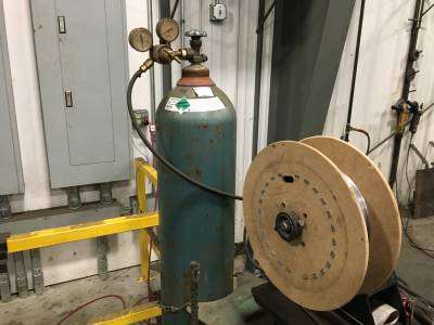
You will also need to choose the right gas and filler wire (or electrode) for a proper weld and adjusted settings. This area also varies quite a bit depending on all of the factors we mention above and a few more as well.
The most commonly used gas and electrode variations and combinations are:
- Carbon Steel: ER70S electrodes with a C25 gas (that’s 75% argon and 25% carbon dioxide).
- Stainless Steel: ER308L with a C2 Gas (that’s 98% argon and 2% carbon dioxide).
- Aluminum: ER4043 with 100% argon gas.
How to Set Up a MIG Welder
There are 3 basic settings or controls that you need to consider when setting up your welder –
- Voltage
- Wire feed speed
- Gas flow rates and gas types and mixtures
These settings are the 3 things that control the heat of your weld. Depending upon what gasses you use, these also contribute to the heat transfer type.
If you’re unfamiliar with these transfer types, then make sure you read up and do some research on MIG welder transfer types. They have a massive impact on your settings and the way you will be welding.
Voltage Settings and Polarity
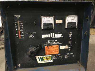
Newer machines no longer need to control the feed wire speed and voltage. Just turn a dial to the thickness you desire for your finished weld and tweak as needed. These machines will do everything for you except regulate your gas flow.
The starting voltage type is almost always the DCEP or Direct Current Electrode Positive. This means that your handle will be on the positive side of the circuit. Another way of saying this is that the electricity will flow from the metal into the welding handle. This setting will rarely ever change. If you ever do need to change it, then you will have to unbolt the internal leads and flop them manually.
The voltage is the main heat setting that will be manually adjusted. This setting will change based on the joint, the thickness of the metal and weld, the type of shielding gas used, and the position of the weld. This setting handles almost all of the regulations. It is the most commonly used knob to change welder settings in the midst of jobs.
The voltage setting will vary based on the size of the electrode that you use, how thick your metal is, and the type of gas you are using. Because MIG welders are usually CV (constant voltage) power sources, the voltage will rarely fluctuate much when welding.
Wire Feed Speed
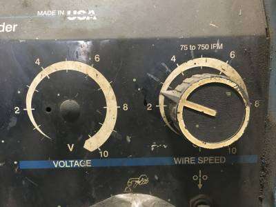
The wire feed speed in a MIG welder will regulate how quickly the wire is fed into the joint and how much of it is fed. Wire feed speed is calculated in inches per minute (or IPM). The wire feed speed is also the setting that dictates the amperage setting, although the voltage is responsible for fluctuating based on the arc length.
With MIG welding, it is the voltage setting that will stay the same. The amperage changes depending upon your wire feed speed and electrode stick-out. The faster the wire gets fed into the joint, the better then contact it will have. The better the contact, the more the amperage will get through the wire. The more the amperage gets through the wire, the higher the heat will be.
Gas Flow Rate and Gas Type and Mixture
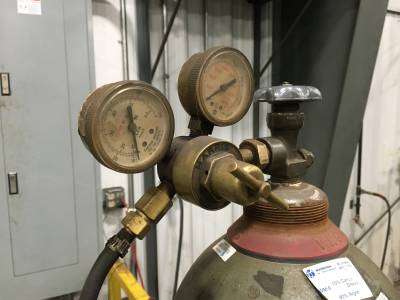
The last factors that affect the welder’s settings are the gas type and gas flow rate. These will help to regulate the transfer type. A higher percentage of argon o helium added to a shielding gas mixture will create a hotter arc.
The main goal of gas settings is to provide enough gas to shield your weld area from the surrounding air. Gas flow rates are regulated in CFM (cubic feet per minute).
Related Article: What Gas Do You Use with a MIG Welder – A Helpful Guide
This area requires a little bit of experimentation on the part of the welder. IN a shop setting, 15 CFM is usually sufficient to shield the weld, but draftier areas may require 50 CFM. ON average, most welders stay between 15 and 20 CFM.
Another thing to be mindful of is that you should never have your gas setting too high. When your flow rate is too fast, it will waste gas and therefore waste money.
It will also cause vibrations and suck in some air, which will result in contamination in your weld. Having the right gas flow rate is an experimental process of trial and error that no chart can provide.
It is essentially a quest for the happy medium in your settings based on your current welding conditions.
Putting Everything Together (Voltage, Wire Feed Speed, and Gas Flow and Gas Type)
Once each set is put together, it will result in the transfer type that you desire. It will finally have enough heat to penetrate the metal properly without burning a hole right through the joint.
This happy ending is mostly a result of trial and error, and the experimentation finally gets the perfect setting for the weld you need to make.
This is great for DIY and home welders. The good news is that welding engineers and professionals have the experience necessary to forego this experimentation.
They already know their welder and its optimal settings for nearly every situation thanks to experiments they did on their own time.
MIG Welding Charts, Setting Guides, and Exact Numerical Answers
If you’re not a huge fan of experimentation and spending money to find your absolute perfect settings, then this next section will offer some shortcuts that should get you successful welds without the trial and error.
The manufacturers of most welding machines have already included either a MIG welding chart or guide in their machine settings that will tell you their ideal numbers.
It is important to remember that two identical welding machines that have been manufactured by the same company at the same time may still run a bit differently.
These charts are only guidelines and starting points. Every machine has been calibrated differently, and the person who services it further changes those calibrations. Welding skill also plays into the performance of each welding machine.
Each chart will usually include the recommended voltage, wire feed speed settings, and gas recommendations for your machine. Each type of metal will have recommended settings for each of these categories on the chart to get you started.
Keep in mind that these are guidelines. They should produce sound welds, but you may need to make some small changes to each set to achieve perfect welds.
Test your settings on some scrap metal that is very similar to the thickness of your weld metal material. You will also want to set the scrap metal in the position you’ll use to weld. This will help you find the best settings for your weld.
Guidelines for Settings
No matter what you choose as your source of power, you need to read your owner’s manual. These are frequently overlooked, but critical to MIG welding operations. They contain all of your safety guidelines and a lot of important information about your best recommendation settings.
These guidelines are for MIG welding steel with solid wire. Aluminum and flux-cored welding will require different methods. Always keep in mind that your joint design, positioning, and other factors will affect your results and your settings. Whenever you achieve a great weld, make sure you record those parameters for future use.
Let your material’s thickness determine the amperage setting you use. As a general guideline, each .001 inch of material thickness will require 1 amp of output. For example, .125 inch thick material will take 125 amps.
You will make your wire size selection based on your determined amperage. Since you rarely want to change your wire, you should choose this based on the thickness you use most frequently. As a guideline ranges from 30 to 130 amps will take .023 inches.
For 40 to 145 amps, you can use .030 inches, which is the most common thickness. The other extremely common thickness is .035 inches, which is what you will use for range from 50 to 180 amps. If you’ve got 75 to 250 amps, then use .045 inch thick wire size. The size is a measurement of the wire’s diameter.
Next, set your voltage. The voltage setting will determine the height and the width of your bead and arc. If you don’t have a chart or any manufacturer recommended specifications available, you can try to experiment. Have one person weld on scrap metal while an assistant turns down the voltage until the arc starts to stub into the workpiece.
Then, weld again and have the assistant increase the voltage until the arc becomes sloppy or unstable. Choose a voltage point that is midway between the point where it stubbed and the point where the arc got sloppy. This will be a good starting point.
There is a tangible relationship between the length of an arc and the voltage of that arc. A longer arc will increase the voltage and result in a wife, flat bead. A shorter arc (less voltage) will result in a narrow, ropey looking bead. If you have too much length to your arc, your bead will become very flat and you may experience undercutting.
Set your wire feed speed last. This speed will control your amperage and determine the penetration of your weld. If your speed is too fast, you may end up burning through your base metal. If a setting chart isn’t available, then you can use this chart as a good starting point for your wire feed speed.
| WIRE SIZE | MULTIPLY BY | EX. USING 1/8 IN. (125 AMP) |
| .023 inches | 3.5 inches per amp | 3.5 x 125 = 437.5 ipm |
| .030 inches | 2 inches per amp | 2 x 125 = 250 ipm |
| .035 inches | 1.6 inches per amp | 1.6 x 125 = 200 ipm |
| .045 inches | 1 inch per amp | 1 x 125 = 125 ipm |
Check Parameters by Examining Your Beads
One of the ways to check your set parameters is by examining your weld beads. The appearance will tell you what you need to adjust. On a good weld, you will see great penetration into the base metal, a nice flat bead profile, the correct bead width, and a great tie-in at the edges where the weld metal meets the base metal.
If you are seeing inconsistent penetration, then you may have set your voltage too high. This results in poor arc control and a turbulent weld pool that can’t consistently penetrate your base material.
On the other hand, if you’re seeing excessive spatter, a convex bead profile, and poor tie-in at the edges of your weld where the metal meets the base, then your voltage may be too low. This results in poor penetration, poor arc starts, and decreased control.
If you’ve got a narrow and convex bead that doesn’t have enough tie-in at the edges where your weld metal meets your base metal, an inconsistent beading, and insufficient penetration, then you’re traveling too quickly. These are all signs of a travel speed that is too fast.
If, on the other hand, your weld bead is way too wide and shows poor penetration and possible bun-through, then you’re traveling too slowly. Traveling too slowly will place too much heat into the weld.
If your weld shows excessively wide beading, burn-through, excessive spatter, and poor penetration then you need to change your amperage and wire feed speed.
These are all signs that your wire feed speed is way too high. On the other hand, if you’ve got a convex and narrow bead with poor tie-in at the edges where the weld metal meets the base metal, then you need to increase your amperage because these are signs that your wire feed speed is too low.
If your weld shows pinholes and porosity in the face and interior of your weld, then you need to adjust your gas flow rate. These are the very clear signs of inadequate shielding gas!
Frequently Asked Questions
While this is a pretty thorough guide for MIG welder settings, some commonly asked questions were not addressed here. Let’s take a look at them and see if we can answer all of your questions.
Do all MIG welders have the same settings?
No. As we mentioned before, each welder performs differently. Not only will the settings be different from manufacturer to manufacturer, but they will also be different from machine to machine, especially after service and calibration.
This is why the ideal settings for each individual welder are usually provided either on the machine or in the user’s manual.
How do I set up a MIG welder for aluminum?
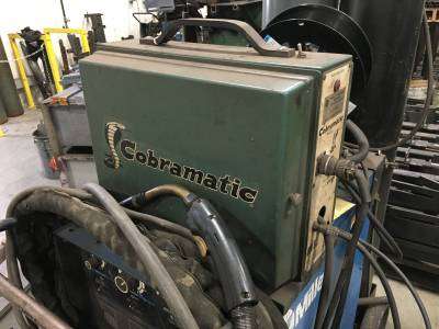
Aluminum welding is possible with MIG welders, but it takes some finesse. Aluminum wires tend to be weaker, stickier, and more expansive than steel wire so you will need some extra steps in your setup to prevent problems with wire feed. Keep in mind that MIG is only a good choice for thick aluminum. If you’re welding thinner aluminum, you may want to consider TIG welding instead.
Because the aluminum wire is so much softer than steel wire, it can easily get crumpled. This will cause birdnesting, or worse – jam your feeder! If you’re not careful, your wire will fold up in your wire feed the second you strike your arc. Most of this is because you’re using the wrong liner or a bad tip.
Because aluminum expands so much more than steel once heated, it can seize inside the brass tip. For this reason, you will want to use an oversized contact tip. For aluminum 0.8 mm thick, use tips designed for 1 mm steel wire instead.
Because the aluminum wire is sticky and can pick up on a steel wire liner, you should replace your steel liner with a plastic one to avoid this issue. Extend the liner as close as you can to the wire rollers to cut down on the distance the aluminum wire will need to travel without the support of the liner. When you cut the distance between the liners and rollers in half, you will decrease your chance of crumpled wire by 75 percent!
You should also use a pure argon shielding gas. A 60l gas bottle should last you for a meter of welding. When it comes to adjusting the wire feed speed, aluminum welding should be twice as fast as steel welding for the same wire diameter.
This will let you use thicker wire flr aluminum, which will be less likely to bird nest in your feeder. Using 1 mm diameter aluminum wire instead of 0.8 mm wire will help, too.
The roller tension can also be reduced by a lot. The rollers will have a much easier time gripping aluminum than they do with steel. Extra tension could cut your wire at a sharp edge, which could wear through your liner and increase friction. Use rollers with a U shape instead of a V shape groove to reduce this issue.
For aluminum, using ER4043 is an extremely common wire type for all-purpose work. If your weld needs more strength and rigidity, you can go with the ER5356 instead.
Make sure that you use 100% argon shielding gas and use the shortest gun possible if you can’t use a spool, and keep your gun as straight as possible.
| Material Thickness | IPM (Inches Per Minute) | IPM (Inches Per Minute) |
| 1/8 Inch | .035 at 300 to 400 ipm | 1.2 mm at 240 to 270 ipm |
| 3/6 Inch | .035 at 425 to 450 ipm | 1.2 mm at 300 to 325 ipm |
| ¼ Inch | 1.2 mm at 350 to 375 ipm | 1.6 mm at 170 to 185 ipm |
| 5/16 Inch | 1.2 mm at 400 to 425 ipm | 1.6 mm at 200 to 210 ipm |
| 3/8 Inch | 1.2 mm at 450 to 480 ipm | 1.6 mm at 220 to 230 ipm |
| 7/16 Inch | 1.6 mm at 240 to 270 ipm | |
| ½ Inch and Up | 1.6 mm at 240 to 270 ipm |
How do I set up a MIG welder for stainless steel?
A lot of stainless steel MIG welding tests use a Tri-mix shielding gas of 90% helium, 7.5% argon, and 2.5% carbon dioxide.
They also use .035 inch 308 stainless steel MIG wire. You can use this and try 20 volts for your setting, with a 300 ipm wire feed speed.
The process for MIG welding stainless steel is much easier than aluminum. Despite that, it has some properties that complicate the process.
Along with the tri-mix of argon, helium, and carbon dioxide, try some of these settings.
| Material Thickness | IPM | Volts | Amps |
| 18 Gauge | .035 at 120 to 150 ipm | 20 volts | 50 to 60 amps |
| 16 Gauge | .035 at 180 to 205 ipm | 20 volts | 70 to 80 amps |
| 14 Gauge | .035 at 230 to 275 ipm | 20 to 21 volts | 90 to 110 amps |
| 12 Gauge | .035 at 300 to 325 ipm | 20 to 21 volts | 120 to 130 amps |
| 3/16 Inch | .035 at 350 to 375 ipm | 21 volts | 140 to 150 amps |
| ¼ Inch | .035 at 400 to 425 ipm | 21 volts | 160 to 170 amps |
| 5/16 Inch | .035 at 450 to 475 ipm | 22 volts | 180 to 190 amps |
| 3/8 Inch | 1.6 mm at 140 to 170 ipm | 25 volts | 250 to 275 amps |
| 7/16 Inch | 1.6 mm at 170 o 200 ipm | 27 volts | 275 to 300 amps |
| ½ Inch | 1.6 mm at 200 to 230 ipm | 32 volts | 300 to 320 amps |
Conclusion
As long as you follow these steps, you will have your MIG welder up and running perfectly in no time at all!
Once you’ve got your starting point, you can adjust your settings in smaller increments based on the results you’re seeing.
We’ve gone over the most common issues with a visual representation, so you will know what to adjust and in which direction based on the issues you notice with your weld’s visual appearance.
We have included some guidelines for starting points in case your welder doesn’t provide a chart. We have even included some common changes that will allow you to MIG weld with stainless steel and aluminum!
Now, all that remains is for you to get your MIG welder set and start welding!

